Table of Contents
General rules of DfAM
The design for AM brings radical changes compared to the design for traditional technologies. Although it removes many of the limitations that apply to traditional manufacturing technologies, AM also introduces some new limitations. Design rules for AM can be divided into:
- General rules for AM design, which are common for all AM technologies, and
- Process-specific design rules, which depend on AM technology that is used.
The section Design for additive manufacturing (DfAM) introduces potentials and advantages of the DfAM strategy that enable significant product improvements. To achieve this, designers have to change their conventional approach to design. General design rules of DfAM serve as guidelines how to take advantage of AM's capabilities in general, while process-specific rules indicate how to overcome certain limitations that apply to specific AM processes and materials.
In the monography "Additive Manufacturing-Developments in Training and Education" and in the book "A Practical Guide to Design for Additive Manufacturing" proposed “The Seven Golden Rules for DfAM”. By their content and clarity, they represent a good foundation for harmonized presentation of DfAM for all AM technologies, and that approach will be followed also in D4AM Wiki. However, the authors of D4AM Wiki will add some of their observations and experiences to that concept.
1. DfAM rule: IT DEPENDS!
Why? Apart from a small number of general rules that can be applied universally to AM, many design parameters depend on production parameters, which, in turn, depend not only on the chosen AM process, but also on the selected material, selected product strategy and other factors. Production parameters may vary from machine to machine, or operator to operator, or even within the same AM process of the same manufacturer.
Example: When apart should have holes, the recommendations on the sizes of hole diameters that may be manufactured with high accuracy depend on the selected AM process, and are defined depending on the thickness and orientation of the wall where the hole is located (see figure below, source: Anubis 3D). The recommendations presented in these figures are give for SLS technology, polyamide PA12 material, layer thickness of 100μm and laser power of 30 W, and adherence to the those rules will in majority of cases lead to successful production by AM under such conditions. However, given that different machines may have different working chamber temperatures, different layer thicknesses, lasers with different powers and different other process parameters, it may happen that these differences cause different accuracy of the diameter of a hole.


Therefore, whenever in doubt, try printing the test part first. If you know the AM process, the machine that the operator will work on, then your job as a designer is easier. With experience in designing for AM, designers gain the ability to design AM parts that will be manufactured without error and without trial production.
2. SHOULD YOU DfAM in first place?
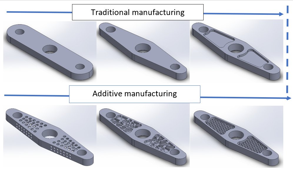
DfAM should be used only if a part cannot be easily made using traditional technologies. Production of parts with simple geometry is more economic and faster with traditional technologies. For example, if a part is designed for machining using a CNC machine with 3 axis, it should not be made by AM. However, when the geometry of the part reaches a level when it may not be manufactured (or it becomes very difficult) using traditional technologies, then AM is the technology of choice.
Example: The figure below shows an example of a lever that may be realized with different complexity of geometry, showing how they can be more suitable for additive or traditional manufacturing technologies.
3. MAKE YOUR DESIGN COMPLEX, it does not cost more!
The original statement of this rule states “make your product beautiful”, but in opinion of authors of D4AM Wiki, the complexity of design offers more quality to a product than just a beauty, as complex design may make a product more useful, lighter, more efficient and less expensive, to mention just some of the advantages.
Anyway, one of the most important advantages of AM is that the AM production costs are independent geometry of the manufactured object. Furthermore, due to lower material consumption, the AM production costs of a product with more complex shapes may be lower than those of the product with the same dimension, but simple geometry.
Therefore, do not use this advantage of AM to optimize the product geometry, but also to give your product a unique aesthetic form, to highlight the company logo and name, part ID marks, instructions, etc.
4. Design with BUILD ORIENTATION in mind!
The orientation of a product during AM building process affects its quality from several aspects:
- strength and other mechanical properties,
- dimensional accuracy and surface quality,
- production costs,
- amount of supports,
- post-processing, etc.
Strength and mechanical properties
The anisotropy of AM process (stacking of product layers along one axis) leads to anisotropy of mechanical properties of the material of the product. The anisotropy may be more or less pronounced, which depends on the selected AM process, as the following table shows:
| Technology | Influence of anisotropy in build direction (vertical direction, z-axis) |
|---|---|
| Material extrusion | Large |
| Photo-polymerization | Medium |
| Polymer powder-bed fusion | Medium to minimal |
| Metal powder-bed fusion | Minimal, may even be eliminated by heat treatment or other post-processing such as hot isostatic pressing (HIP) |
Due to the anisotropy, the tensile strength and other mechanical properties of products are weaker along the build direction. For that reason, horizontal and slanted orientations of the axis that will be subjected to loads during exploitation bring higher load capacities than the vertical build orientation of the part axis. In the lower part of following figure are shown three orientations of a stick, with indication that the stick that is built with vertical longitudinal axis will be weaker than the sticks built with horizontal or slanted orientation of the axis.
Example: The upper part of the figure on left side shows two cylinders; the cylinder on the left is built with vertical longitudinal axis and horizontal circular cross-sections, while the cylinder on the right is built with horizontal longitudinal axis and vertical circular cross-sections.
The lower part of the figure shows three sticks, built with longitudinal axis in slanted, horizontal and vertical orientation.
, accuracy and surface quality (high/low) and duration of production process")
The figure shows influence of build orientation to mechanical strength (strong/weak), accuracy and surface quality (high/low) and duration of production process, which is explained in the text of appropriate sections.
Dimensional accuracy and surface quality
The anisotropy of the structure and AM product properties, which arises as a consequence of the anisotropy of the build process, leads further to anisotropic shrinking of the products after the manufacturing process is completed. For this reason the dimensional accuracy. The figure above shows that the circular shapes built in the vertical plane are, due to the anisotropic shrinking, deformed, leading to lower dimensional accuracy. On the other hand, the circular shapes built in the horizontal plane remain circular, leading to higher dimensional accuracy.
The layerwise structure of AM products may lead to the degradation of the surface quality due to the different shapes of subsequent layers, which is called “the staircase effect”. The surfaces that are built with small slopes (angle to horizontal) are particularly sensitive to the “staircase effect” because the difference between the dimensions of their vertical cross-sections is larger than in the case of surfaces with higher slopes. The figure above shows that the lateral surface of the cylinder built with longitudinal axis in vertical direction will have higher surface quality than the lateral surface of the cylinder built with longitudinal axis in horizontal direction. The top right part of the figure shows the cross-section of cylinder built with longitudinal axis in horizontal direction, with visible “staircase effect.
Production costs
The build orientation of a part determines the number of layers that should be deposited during the build process. The number of deposited layers affects the duration of production process) and for number of technologies, the consumption of raw material and consumables. Therefore, the build orientation of products affect material costs and energy and equipment costs of the AM production process, thus influencing the prices of the products. The figure above indicates that the duration of manufacturing of parts with vertical orientation of longitudinal axis is longer then production of the parts with other orientations of longitudinal axis.
If there are no other specific requirements, then the orientation of parts during production is optimized to reduce the number of layers, and this reduce AM production costs.
5. Design to AVOID SUPPORTS!
Most AM processes require the creation of load bearing structures - supports, created to to prevent deformation of the suspended structures (drains, large cavities, sloped surfaces) and ensure the static stability of the product during building, as well as to facilitate heat dissipation, which is especially important during AM of metal parts. In a case of inadequate design of the supports, large residual stresses, which arise as a result of non-uniform cooling, may cause deformation of the manufactured AM part during or after the building.
There are several reasons in favor of the recommendation that the supports should be reduced as much as it is possible. They prolong the duration of manufacturing process, increase the consumption of material, degrade the surface quality of the products, and consequently increase the post-processing costs. In addition, if placed on locations that are not easy to access, removal of the supports may be very difficult and time-consuming.
Proper orientation of the parts and application of the design rules for AM during the modeling of the products may enable suitable positioning of the supports, or - in the best case scenario - completely remove the need for supports.
Example: A rectangular shape with opening like in the top left image of the figure (source 3DPrint) cannot be built because of the existence of the downward facing surface over the top side of the opening; the problem may be solved in different ways. The first approach is building of the supports without re-orientation or re-design of the part (a). The image in top center shows supports that join the downward facing structure to the upward facing surface at the bottom of the opening; however, such support would degrade the surface quality of both joined surfaces. The figure on top right shows supports that join the downward facing structure to baseplate, avoiding degradation of the surface quality of the upward facing surface at the bottom of the opening.

The image on the bottom left (b) shows that the re-orientation of the build orientation of the product reduces downward faced surfaces, thus reducing needs for the supports just to the area around one vertex of the product; however, the slope of the surfaces will lead to small “staircase effect” and slightly degrade the surface quality of the sides of the product. The image in the bottom center © shows that the re-design of the product with pillars in the opening completely removes the need for supports. However, if a large opening is required, then the opening may be re-designed to have top surface in the form of a series of triangles, as on the image in the bottom right (d), so that thin supports of between the triangles, which join the two sides of the opening, will be sufficient to build the top surface of the opening; due to their small thickness, their removal is easy, and the degradation of the surface quality of sides of the opening is minimal.
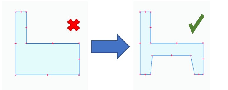
6. AVOID EXCESSIVE MATERIAL!
The authors of the D4AM Wiki opted to avoid the expression “large masses” for big chunks of material since “reduction of mass” is also topic of lightweight design, which sometimes may lead to confusion. We admit, though, that we are not particularly happy about the term “excessive material” (maybe “un-necessary” is the best for description of the the rule, but we find it too clumsy). Diegel, Nordin and Motte in their great book “A Practical Guide to Design for Additive Manufacturing” use also the term “superfluous”, which is a synonym for “excessive”. The authors will welcome any recommendations for improving of the term.
Design for machining recommends to leaving intact the material without functional relevance in order to avoid wasting of time and money on removal of the material by machining. On the contrary, such excessive material in AM design represents much bigger problem, as it profoundly increases duration of the production process and consumption of expensive raw materials and consumables. Therefore, the excessive material represents profound increase of costs for AM technologies. Furthermore, large amounts of material are the source of increased residual stresses and represent the potential source of deformations of a product. Therefore, the excessive material has serious negative impacts for AM technology products and should be avoided by proper design of products.
Example: As a general rule, designers should avoid any increase of uniform thickness of a part without proper reason The shape on the left image has higher thickness of the lower part than in the upper part. If there are no functional or other requests, it may be re-designed as shown in the right image, where the shape has the same thickness in all its parts.
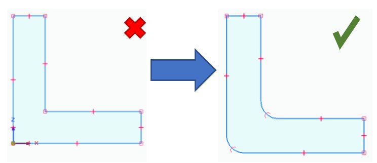
7. FILLET EVERYTHING to avoid stress concentrations!
Sharp corners, and especially the internal ones, are strong sources of stress concentration and should be avoided in general. However, because of the sensitivity of the AM production process to internal stresses, this rule represents absolute request for AM designers. The rule requires to fillet all the sharp edges, since production of such shapes will not increase the AM costs. Apart from reduction of stresses, the products without sharp corners are ergonomic, more comfortable to use.
Example: As a general rule, It is recommended that the size of the filleting radius should be about ¼ the thickness of the shape. The shape on the left image has a rectangular corner in the lower left part. If there are no functional or other requests, it may be re-designed as shown in the right image, where the edges around the vertex of the corners are filleted.