
Table of Contents
Design for additive manufacturing (DfAM)
DfAM is a strategy that challenges industrial and mechanical designers to transcend the existing design paradigms, which guide and constrain designers when they design for traditional manufacturing technologies. Sometimes DfAM only involves redesign of existing parts for additive manufacturing (AM), for example, to reduce the mass or to consolidate several parts into one. However, one should not stop there, and should think in the direction of changing the internal and external geometry of products to improve the function or to customize their shape and function to needs of individuals or groups of users.
Optimization of product geometry based on the DfAM methodologies refers to specific design techniques that need to be developed to maximize the potentials of AM. These techniques are:
- Light-weight design (Complex design)
- Topology optimization
- Application of bionic principles and transformation of shapes from nature
- Lattice and cellular structures
- Component consolidation (design of integrated geometries - several parts connected into one functional unit)
- Design for functional integration - multifunctionality achieved by shape
- Design to improve the function and performance of the work
- Tool optimization
- Customization
Lightweight design (Complex design)
The freedom in creating the geometry offered by AM enables design of the parts according to the same functional requirements as conventional parts, but with less material, which is called “lightweight design”.
Topology optimization
Topological optimization of parts for AM is done to achieve the following goals: mass reduction, stress reduction (i.e., elimination or reduction of stress concentration), obtain a uniform voltage distribution and reduce waste during production.
Example: EADS (now Airbus Defence and Space) has applied topological optimization for DMLS technology, redesigning nacelle hinge brackets for aircraft engine cowlings. By optimizing the topology were achieved savings in material consumption, which was reflected in the savings in fuel consumption and in the reduction of harmful gas emissions (see next figure, source additivemanufacturing.global).

Bionic design
Designing products by emulating shapes from nature goes a step further in topology optimization. After the phase of topological optimization using mathematical methods, the shaping of parts follows by mimicking structures from nature.
Example: The following picture (source Applied Sciences journal) shows an example of a redesign of a mechanical component inspired by the structure of a branched fishbone structure.

The image a) shows the conventional design, and the image b) shows bionic design. “Redesign of the part is a bio-inspired idea of “main-branch and sub-branch”. It is based on bionic design method for skeleton structures with complex features. The bionic design of a control arm is carried out by the method: structural main-branch is obtained by the load path analysis and structural sub-branch is occupied by the fish-bone structure. Result: structural stiffness is increased by 62.3%, while the weight is reduced by 24.75%.” (citation from the article "Novel Bionic Design Method for Skeleton Structures Based on Load Path Analysis" by Zhang et al.)
Lattice and cellular structures
Lattice and cellular structures represent a type of complex designs used for topological optimization for AM. These are structures that consist of unit cells made of nodes and rods (or load-bearing walls) that periodically repeat in space. By combining different densities of nets, distances between nodes, wall thicknesses and cell shapes, one may adjust the mechanical characteristics of these structures.
Example1: Reduction of mass of a hinge by replacing of low-stressed parts by lattice structure (source: 3D incredible ).

Example 2: Advanced “smart” football helmet (Riddell's Speedflex Precision Diamond helmet, source: TCT magazine) with personalized liner pads that fit individual players, realized as a lattice structure.


Component consolidation
Conventional technologies often impose on designers the need to simplify parts of complex geometry by dividing them into several simpler elements. The final shape is then obtained only after the assembly or welding process. AM, on contrary, allows integration of geometries, i.e. combining of elements adjusted for traditional production technologies to obtain a more complex part, which will be produced as a whole in a single process. This means that the geometry and function of a single AM part will correspond to the geometry and function of a whole set of elements after assembly or welding. This process is called “component consolidation” or “consolidation of parts” in the literature. The consolidated part is also lighter than the assembly for two reasons: first, due to the omission of additional connecting elements (screws, nuts, etc.), and second, due to the possibility for topology optimization during the redesign.
Example: General Motors applied parts consolidation to improve design of a seat bracket, a small but safety critical part that secures seat-belt fasteners to seats and seats to floor. Using generative design and AM, its engineers succeeded to integrate eight different components of the seat bracket into one AM part (see figure below, source Autodesk). The redesigned stainless steel part (on the right side of the figure) is 40% lighter and 20% stronger than the initial solution (on the left side of the figure).

Design for functional integration
“Functional design” mainly means unification of multiple kinematic functions in an assembly, which can be produced as a single part in one AM process, but requires production of several parts, assembly and adjustment when it is produced by traditional technologies. In most cases, the design for functional integration comprises the design for AM of moving parts with joints, such as various assemblies with hinges, sliders, guides and similar components that are, by redesign, joined in a single part.
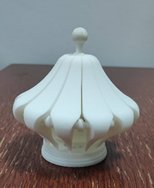
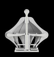
Example: An example of functional integration is presented in figure below (design of Marko Todorović, a participant in the competition "ImPossible Design 2019"). It presents a decorative box designed for AM with the aim to, using an appropriate geometry (image in the middle of the figure), enable the motion of the part in such a way that the box may be closed (image on the left side of the figure), completely open (image on the right side of the figure), or held in any selected position between those two extremes. When designing movable objects, it is important to account for the sufficient clearances between its parts that will move relative to one another. The clearances depend on AM technology for production of the object.

Design for improved function and performances
The important property of AM to produce objects of almost arbitrary shapes enables the creation of machine parts of complex geometry, with thin walls and internal channels and cavities. Such mechanical structures have superior fluid flow properties because they offer the ability to control direction that other technologies cannot achieve, which is of great importance for the flow of fuel, air or coolant.
Example: The example shows a turbine blade with significantly improved key design performances enabled by AM technologies. The complex external shape of a turbine blade is only one side of the problem (see top image on the figure, source EOS). Design and production of internal cooling channels are equally demanding problems, especially from the aspects of their geometry and size of cross-section. Their role is to cool the blade when the high operating temperature of the environment, which increases efficiency, exceeds the melting temperature of the material from which the blades are made. Different types of channels can be used to cool the blade surface, and the images in the bottom row of the figure shows two innovative solutions for their design (sources WIT Press for image left side and International Journal of Current Engineering and Technology for image on right side).


Tool optimization
Another important application of design for function and performance improvement is the production of plastic injection tools or blowing tools with conformal cooling channels.
With these tools, it is necessary to provide additional cooling, i.e. tempering (setting the optimal, uniform temperature filed over the surface of a tool), which is achieved by introducing internal channels through which the coolant liquid flows at the appropriate temperature. When this type of tool is made with conventional technologies, the shape of these channels is limited to combinations of straight lines. Additive technologies enable production of tool inserts with internal channels for conformal cooling, in which the channels follow the contour of the tool at an optimal distance from the surface of the tool. Conformal channels, in addition to being able to follow the contour of the mold, are not limited to circular cross section, but can be optimized according to the requirements of mold temperature control, so they may have oval, triangular or any other shape. Such channels allow the coolant to pass through the mold in accordance with the shape of the mold cavity, which further ensures uniform and faster cooling. The process of design of a tool is based on combination of standard components (using the traditional technologies of making tools) and innovative components (inserts) made by AM.
Example: EOS designers developed the tool for injection moulding of plastic cups (the figure below, source: MachineDesign), which reduced the duration of production cycle from 24 seconds (for the traditional design tool on top left image) to 13.8 seconds (for the tool with inserts with conformal cooling channels). The tool is manufactured from maraging steel MS1 using DMLS technology and design rules for tool optimization.

Customization
Customization design means adapting the product to the needs (requirements) of a specific user (customer) or a specific group of customers. One of the most important advantages of AM technology is that they can manufacture different parts in one production process without additional costs, which makes them the optimal solution for production of customized products. In this way, these technologies make are transforming the concept of mass production of identical parts into mass production of customized, mutually different, parts.
Individual design has the most important and the greatest role medical and dentistry applications. AM is used to directly manufacture personalized prostheses, splints and fixators that provide better comfort to the patient, because the shape is adapted to his constitution and body shape.
Examples: The orthoses shown in the figure below (on the left image, an orthose made by Ottobock, and on the right image, a foot orthose and an upper body orthosis, source: EOS) , have several advantages compared to traditional orthoses, as they are lighter, breathable, tailored to the user and adapted to their individual needs.

